ASA CHAPTER 2 (OSPF & ADVANCED ROUTING)
3. What are the configurations step for OSPF ?
• Create OSPF routing process in the ASA firewall using the OSPF process
ID 1 and the OSPF router-ID of 150.X.12.12.
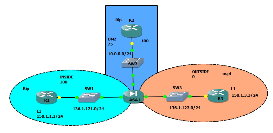
• Assign interfaces to OSPF areas per the diagram provided.
• Ensure the ASA is never elected as DR on segment.
• Authenticate the OSPF adjacency across “outside” interface using
interface-level commands only. Use the password of “CISCO” and most
secure form of authentication.
4. How to perform SLA-tracking & redistribution ?
• Implement a reliable default route towards R3 in the firewall. Track R3’s
Loopback1 reachability for that.
• Redistribute RIP routes into OSPF.
• Originate the default route into RIPv2.
-->
Solution:
3. What are the configurations step for OSPF ?
• Create OSPF routing process in the ASA firewall using the OSPF process
ID 1 and the OSPF router-ID of 150.X.12.12.2.
• Assign interfaces to OSPF areas per the diagram provided.
• Ensure the ASA is never elected as DR on segment.
• Authenticate the OSPF adjacency across “outside” interface using
interface-level commands only. Use the password of “CISCO” and most
secure form of authentication.
-->
OSPF
configuration steps:
1) (Mandatory). Enabling OSPF process with a certain process-ID (there could
be multiple OSPF process in a single box) and assigning a router-ID, which
identifies the box in the OSPF topology. If you do not assign a router-ID the ASA
will pick it up for you automatically. However, it is generally a good practice to
assign it manually, to ease the troubleshooting.
2) (Mandatory). Configuring the networkstatements to identify the interfaces
where OSPF should establish adjacencies. The syntax is network <subnet>
<subnet-mask>and is different from the syntax used in the IOS routers, where
you use the wildcardmask. Every interface that has the IP address matching the
configured network statement is selected for establishing OSPF adjacencies. In
addition to that, the subnets for those interfaces are advertised as OSPF links
and become accessible to the other OSPF routers. Note that OSPF configuration
does not support the passive-interfacestatement, but accepts various
network scopes.
3) (Optional). Designate some interfaces as passive for OSPF. Unlike RIPv2,
however, passive OSPF cannot establish OSPF adjacency and exchange link
stats. Thus, a passive interface is advertised into OSPF but not used for any
routing information exchange.
4) (Optional). Configure the ASA unit as designated or non-designated router on
the active OSPF interfaces. Designated OSPF routers (DRs) are used on shared
interfaces, like Ethernet, to centralize routing information exchange. Commonly,
a DR is the most powerful and stable router on the segment. By default, the first
router to boot up and initialize is elected as DR. If there are many routers
conquering for the DR role, the one with highest OSPF interface priority is
selected as the DR. If the priorities match, the router with the highest Router-ID is
elected as the DR. If you set the OSPF priority to zero on a given interface, the
ASA will not even attemptto become a DR. Note that the router might be a DR
on one segment and non-DR on another. Manipulating priorities might be
needed, as the default value is one, which might result in non-deterministic DR
elections.
And the most important thing of OSPF configuration from the security standpoint
is protocol authentication. OSPF authenticates allOSPF packets (authentication
is a part of OSPF header, and OSPF has the IP protocol number of 89) supports
threetypes of authentication: null (empty), plain-text (clear text password) and
secure MD5 hash over the packet contents. Note that OSPF authenticates the
packet exchange on a given segment connection. You may define various
authentication types on different interfaces. First, look at the authentication types:
1) NULL – explicitly states that the packet is not authenticated.
2) Plain-text – carries a password in the header. Only one password is allowed.
3) MD5-hash – carries a key ID along with the corresponding hash value in the
header. There could be different key IDs, and the receiving router selects the
appropriate local key based on the key ID in the header. You can configure
multiple keys on a single interface, and the router will send packets authenticated
with every active key.
You can enable OSPF authentication on the interface using the commands ospf
authenticationfor the ASA or ip ospf authenticationfor the IOS
routers. To set the MD5 keys, use the commands ospf message-digest-key
and ip ospf message-digest-keyrespectively. Using this command you
set the mode and the respective keys on the particular interface. Alternatively,
you can use the process-level command area X authentication
[message-digest]to enable authentication on all interfaces that are members
of the particular area. You still need to configure the keys at interface level
however.
---->diagram:
on ASA:
!
interface Ethernet0/0
nameif outside
security-level 0
ip address 136.1.122.12 255.255.255.0
ospf priority 0
ospf authentication-key CISCO
ospf authentication message-digest
!
!
router ospf 1
router-id 150.1.12.12
network 136.1.122.0 255.255.255.0 area 0
log-adj-changes
redistribute rip metric 444 subnets
!
A# sh route
Codes: C - connected, S - static, I - IGRP, R - RIP, M - mobile, B - BGP
D - EIGRP, EX - EIGRP external, O - OSPF, IA - OSPF inter area
N1 - OSPF NSSA external type 1, N2 - OSPF NSSA external type 2
E1 - OSPF external type 1, E2 - OSPF external type 2, E - EGP
i - IS-IS, L1 - IS-IS level-1, L2 - IS-IS level-2, ia - IS-IS inter area
* - candidate default, U - per-user static route, o - ODR
P - periodic downloaded static route
Gateway of last resort is not set
C 136.1.121.0 255.255.255.0 is directly connected, inside
C 136.1.122.0 255.255.255.0 is directly connected, outside
C 10.0.0.0 255.255.255.0 is directly connected, dmz
O 150.1.3.3 255.255.255.255 [110/11] via 136.1.122.3, 0:03:39, outside
on R3:
R3#sh run int fa0/0
Building configuration...
Current configuration : 169 bytes
!
interface FastEthernet0/0
ip address 136.1.122.3 255.255.255.0
ip ospf authentication message-digest
ip ospf authentication-key CISCO
duplex auto
speed auto
end
R3#sh run | se ospf
ip ospf authentication message-digest
ip ospf authentication-key CISCO
router ospf 1
log-adjacency-changes
network 136.1.122.0 0.0.0.255 area 0
network 150.1.3.3 0.0.0.0 area 0
output:
R3#sh ip route ospf
136.1.0.0/24 is subnetted, 2 subnets
O E2 136.1.121.0 [110/444] via 136.1.122.12, 00:03:41, FastEthernet0/0
10.0.0.0/24 is subnetted, 1 subnets
O E2 10.0.0.0 [110/444] via 136.1.122.12, 00:03:37, FastEthernet0/0
4. How to perform SLA-tracking & redistribution ?
• Implement a reliable default route towards R3 in the firewall. Track R3’s
Loopback1 reachability for that.
• Redistribute RIP routes into OSPF.
• Originate the default route into RIPv2.
-->
The CCIE Security lab most likely will not require you to perform advanced
routing protocols tuning. However, some basic routing features should be known
by every candidate. This task requires you to redistribute between the routing
protocols. That means you should inject other protocols routing information into
another routing protocol. This is needed to obtain full reachability between the
routing domains connected by the firewall.
The main command you need to know is the one entered within the routing
protocol context: redistribute <Source-Protocol> metric <SeedMetric>. For example:
router rip
redistribute ospf 1 metric 1
redistribute static
Pay attention to the <Seed-Metric>. This metric is needed practically all the
time, if only you are not redistributing “connected” or “static” routes. It specifies
the initial metric to be assigned to the redistributed routes. The metric is in the
units understood by the “target” routing protocol. Also, note that using the
“redistribute connected” is another way of advertising the locally connected
interfaces into a routing protocol.
Instead of redistributing routing information into a protocol, you may simply
originate a default route into the protocol. To do that with RIPv2 or OSPF, use
the command default-information originate. This command will always
advertise a default route into RIPv2; however it will advertise the default route
into OSPF if this route exists in the local routing table. If you want the route to be
always advertised into OSPF, use the command default-information
originate always. As for EIGRP, there is no special command to originate a
default route there. However, you may use the command redistribute
staticto advertise the local static default route into EIGRP as well.
Another important routing feature is static reliable routing. It allows you creating a
special “tracker” that pings a destination and reports the reachability state. The
tracker could be associated with the static route, making the route active only
when the tracker is “up”. This might be very helpful with static routes, as you can
track the actual reachability of the next hop. For example, you may configure a
primary route via a route, and track the next-hop reachability. If the tracker would
fail, the secondary static route will preempt the primary one, and the traffic will
flow via the backup path.
You configure a tracker in two steps:
1) Creating a new SLA monitor operation (SLA = Service Level Agreement)
which constantly pings a destination and reports the reachability. You may tune
the following two parameters: timeout(the time to expire every probe, in ms)
and frequency(how often to send the probes). The more often you ping, the
faster you will detect the loss of connectivity. However, this might cause frequent
flaps in case of unstable network.
2) Creating a tracking object using the trackcommand and attach it to a static
route. The tracking object will reference the SLA operation number, and the static
route will reference the tracking object number.
The backup static route should point to the same destination by have numerically
higher distance, signaling its lower preference. E.g.
route outside 0 0 <IP> <Distance>.The default <Distance>value is
“1” and it is assigned to the primary static route.
-->

sla monitor 1
type echo protocol ipIcmpEcho 150.1.3.3 interface outside
timeout 1000
frequency 1
sla monitor schedule 1 life forever start-time now
no crypto isakmp nat-traversal
!
track 1 rtr 1 reachability
!
!
router rip
network 10.0.0.0
network 136.1.0.0
passive-interface default
default-information originate
version 2
no auto-summary
!
!
route outside 0.0.0.0 0.0.0.0 136.1.122.3 1 track 1
!
output:
A# sh track
Track 1
Response Time Reporter 1 reachability
Reachability is Up
1 change, last change 00:03:08
Latest operation return code: OK
Latest RTT (millisecs) 20
Tracked by:
STATIC-IP-ROUTING 0
!
A# sh route
Codes: C - connected, S - static, I - IGRP, R - RIP, M - mobile, B - BGP
D - EIGRP, EX - EIGRP external, O - OSPF, IA - OSPF inter area
N1 - OSPF NSSA external type 1, N2 - OSPF NSSA external type 2
E1 - OSPF external type 1, E2 - OSPF external type 2, E - EGP
i - IS-IS, L1 - IS-IS level-1, L2 - IS-IS level-2, ia - IS-IS inter area
* - candidate default, U - per-user static route, o - ODR
P - periodic downloaded static route
Gateway of last resort is 136.1.122.3 to network 0.0.0.0
C 136.1.121.0 255.255.255.0 is directly connected, inside
C 136.1.122.0 255.255.255.0 is directly connected, outside
C 10.0.0.0 255.255.255.0 is directly connected, dmz
O 150.1.3.3 255.255.255.255 [110/11] via 136.1.122.3, 0:05:55, outside
S* 0.0.0.0 0.0.0.0 [1/0] via 136.1.122.3, outside
!
3. What are the configurations step for OSPF ?
• Create OSPF routing process in the ASA firewall using the OSPF process
ID 1 and the OSPF router-ID of 150.X.12.12.
• Assign interfaces to OSPF areas per the diagram provided.
• Ensure the ASA is never elected as DR on segment.
• Authenticate the OSPF adjacency across “outside” interface using
interface-level commands only. Use the password of “CISCO” and most
secure form of authentication.
4. How to perform SLA-tracking & redistribution ?
• Implement a reliable default route towards R3 in the firewall. Track R3’s
Loopback1 reachability for that.
• Redistribute RIP routes into OSPF.
• Originate the default route into RIPv2.
-->
Solution:
3. What are the configurations step for OSPF ?
• Create OSPF routing process in the ASA firewall using the OSPF process
ID 1 and the OSPF router-ID of 150.X.12.12.2.
• Assign interfaces to OSPF areas per the diagram provided.
• Ensure the ASA is never elected as DR on segment.
• Authenticate the OSPF adjacency across “outside” interface using
interface-level commands only. Use the password of “CISCO” and most
secure form of authentication.
-->
OSPF
configuration steps:
1) (Mandatory). Enabling OSPF process with a certain process-ID (there could
be multiple OSPF process in a single box) and assigning a router-ID, which
identifies the box in the OSPF topology. If you do not assign a router-ID the ASA
will pick it up for you automatically. However, it is generally a good practice to
assign it manually, to ease the troubleshooting.
2) (Mandatory). Configuring the networkstatements to identify the interfaces
where OSPF should establish adjacencies. The syntax is network <subnet>
<subnet-mask>and is different from the syntax used in the IOS routers, where
you use the wildcardmask. Every interface that has the IP address matching the
configured network statement is selected for establishing OSPF adjacencies. In
addition to that, the subnets for those interfaces are advertised as OSPF links
and become accessible to the other OSPF routers. Note that OSPF configuration
does not support the passive-interfacestatement, but accepts various
network scopes.
3) (Optional). Designate some interfaces as passive for OSPF. Unlike RIPv2,
however, passive OSPF cannot establish OSPF adjacency and exchange link
stats. Thus, a passive interface is advertised into OSPF but not used for any
routing information exchange.
4) (Optional). Configure the ASA unit as designated or non-designated router on
the active OSPF interfaces. Designated OSPF routers (DRs) are used on shared
interfaces, like Ethernet, to centralize routing information exchange. Commonly,
a DR is the most powerful and stable router on the segment. By default, the first
router to boot up and initialize is elected as DR. If there are many routers
conquering for the DR role, the one with highest OSPF interface priority is
selected as the DR. If the priorities match, the router with the highest Router-ID is
elected as the DR. If you set the OSPF priority to zero on a given interface, the
ASA will not even attemptto become a DR. Note that the router might be a DR
on one segment and non-DR on another. Manipulating priorities might be
needed, as the default value is one, which might result in non-deterministic DR
elections.
And the most important thing of OSPF configuration from the security standpoint
is protocol authentication. OSPF authenticates allOSPF packets (authentication
is a part of OSPF header, and OSPF has the IP protocol number of 89) supports
threetypes of authentication: null (empty), plain-text (clear text password) and
secure MD5 hash over the packet contents. Note that OSPF authenticates the
packet exchange on a given segment connection. You may define various
authentication types on different interfaces. First, look at the authentication types:
1) NULL – explicitly states that the packet is not authenticated.
2) Plain-text – carries a password in the header. Only one password is allowed.
3) MD5-hash – carries a key ID along with the corresponding hash value in the
header. There could be different key IDs, and the receiving router selects the
appropriate local key based on the key ID in the header. You can configure
multiple keys on a single interface, and the router will send packets authenticated
with every active key.
You can enable OSPF authentication on the interface using the commands ospf
authenticationfor the ASA or ip ospf authenticationfor the IOS
routers. To set the MD5 keys, use the commands ospf message-digest-key
and ip ospf message-digest-keyrespectively. Using this command you
set the mode and the respective keys on the particular interface. Alternatively,
you can use the process-level command area X authentication
[message-digest]to enable authentication on all interfaces that are members
of the particular area. You still need to configure the keys at interface level
however.
---->diagram:
on ASA:
!
interface Ethernet0/0
nameif outside
security-level 0
ip address 136.1.122.12 255.255.255.0
ospf priority 0
ospf authentication-key CISCO
ospf authentication message-digest
!
!
router ospf 1
router-id 150.1.12.12
network 136.1.122.0 255.255.255.0 area 0
log-adj-changes
redistribute rip metric 444 subnets
!
A# sh route
Codes: C - connected, S - static, I - IGRP, R - RIP, M - mobile, B - BGP
D - EIGRP, EX - EIGRP external, O - OSPF, IA - OSPF inter area
N1 - OSPF NSSA external type 1, N2 - OSPF NSSA external type 2
E1 - OSPF external type 1, E2 - OSPF external type 2, E - EGP
i - IS-IS, L1 - IS-IS level-1, L2 - IS-IS level-2, ia - IS-IS inter area
* - candidate default, U - per-user static route, o - ODR
P - periodic downloaded static route
Gateway of last resort is not set
C 136.1.121.0 255.255.255.0 is directly connected, inside
C 136.1.122.0 255.255.255.0 is directly connected, outside
C 10.0.0.0 255.255.255.0 is directly connected, dmz
O 150.1.3.3 255.255.255.255 [110/11] via 136.1.122.3, 0:03:39, outside
on R3:
R3#sh run int fa0/0
Building configuration...
Current configuration : 169 bytes
!
interface FastEthernet0/0
ip address 136.1.122.3 255.255.255.0
ip ospf authentication message-digest
ip ospf authentication-key CISCO
duplex auto
speed auto
end
R3#sh run | se ospf
ip ospf authentication message-digest
ip ospf authentication-key CISCO
router ospf 1
log-adjacency-changes
network 136.1.122.0 0.0.0.255 area 0
network 150.1.3.3 0.0.0.0 area 0
output:
R3#sh ip route ospf
136.1.0.0/24 is subnetted, 2 subnets
O E2 136.1.121.0 [110/444] via 136.1.122.12, 00:03:41, FastEthernet0/0
10.0.0.0/24 is subnetted, 1 subnets
O E2 10.0.0.0 [110/444] via 136.1.122.12, 00:03:37, FastEthernet0/0
4. How to perform SLA-tracking & redistribution ?
• Implement a reliable default route towards R3 in the firewall. Track R3’s
Loopback1 reachability for that.
• Redistribute RIP routes into OSPF.
• Originate the default route into RIPv2.
-->
The CCIE Security lab most likely will not require you to perform advanced
routing protocols tuning. However, some basic routing features should be known
by every candidate. This task requires you to redistribute between the routing
protocols. That means you should inject other protocols routing information into
another routing protocol. This is needed to obtain full reachability between the
routing domains connected by the firewall.
The main command you need to know is the one entered within the routing
protocol context: redistribute <Source-Protocol> metric <SeedMetric>. For example:
router rip
redistribute ospf 1 metric 1
redistribute static
Pay attention to the <Seed-Metric>. This metric is needed practically all the
time, if only you are not redistributing “connected” or “static” routes. It specifies
the initial metric to be assigned to the redistributed routes. The metric is in the
units understood by the “target” routing protocol. Also, note that using the
“redistribute connected” is another way of advertising the locally connected
interfaces into a routing protocol.
Instead of redistributing routing information into a protocol, you may simply
originate a default route into the protocol. To do that with RIPv2 or OSPF, use
the command default-information originate. This command will always
advertise a default route into RIPv2; however it will advertise the default route
into OSPF if this route exists in the local routing table. If you want the route to be
always advertised into OSPF, use the command default-information
originate always. As for EIGRP, there is no special command to originate a
default route there. However, you may use the command redistribute
staticto advertise the local static default route into EIGRP as well.
Another important routing feature is static reliable routing. It allows you creating a
special “tracker” that pings a destination and reports the reachability state. The
tracker could be associated with the static route, making the route active only
when the tracker is “up”. This might be very helpful with static routes, as you can
track the actual reachability of the next hop. For example, you may configure a
primary route via a route, and track the next-hop reachability. If the tracker would
fail, the secondary static route will preempt the primary one, and the traffic will
flow via the backup path.
You configure a tracker in two steps:
1) Creating a new SLA monitor operation (SLA = Service Level Agreement)
which constantly pings a destination and reports the reachability. You may tune
the following two parameters: timeout(the time to expire every probe, in ms)
and frequency(how often to send the probes). The more often you ping, the
faster you will detect the loss of connectivity. However, this might cause frequent
flaps in case of unstable network.
2) Creating a tracking object using the trackcommand and attach it to a static
route. The tracking object will reference the SLA operation number, and the static
route will reference the tracking object number.
The backup static route should point to the same destination by have numerically
higher distance, signaling its lower preference. E.g.
route outside 0 0 <IP> <Distance>.The default <Distance>value is
“1” and it is assigned to the primary static route.
-->
sla monitor 1
type echo protocol ipIcmpEcho 150.1.3.3 interface outside
timeout 1000
frequency 1
sla monitor schedule 1 life forever start-time now
no crypto isakmp nat-traversal
!
track 1 rtr 1 reachability
!
!
router rip
network 10.0.0.0
network 136.1.0.0
passive-interface default
default-information originate
version 2
no auto-summary
!
!
route outside 0.0.0.0 0.0.0.0 136.1.122.3 1 track 1
!
output:
A# sh track
Track 1
Response Time Reporter 1 reachability
Reachability is Up
1 change, last change 00:03:08
Latest operation return code: OK
Latest RTT (millisecs) 20
Tracked by:
STATIC-IP-ROUTING 0
!
A# sh route
Codes: C - connected, S - static, I - IGRP, R - RIP, M - mobile, B - BGP
D - EIGRP, EX - EIGRP external, O - OSPF, IA - OSPF inter area
N1 - OSPF NSSA external type 1, N2 - OSPF NSSA external type 2
E1 - OSPF external type 1, E2 - OSPF external type 2, E - EGP
i - IS-IS, L1 - IS-IS level-1, L2 - IS-IS level-2, ia - IS-IS inter area
* - candidate default, U - per-user static route, o - ODR
P - periodic downloaded static route
Gateway of last resort is 136.1.122.3 to network 0.0.0.0
C 136.1.121.0 255.255.255.0 is directly connected, inside
C 136.1.122.0 255.255.255.0 is directly connected, outside
C 10.0.0.0 255.255.255.0 is directly connected, dmz
O 150.1.3.3 255.255.255.255 [110/11] via 136.1.122.3, 0:05:55, outside
S* 0.0.0.0 0.0.0.0 [1/0] via 136.1.122.3, outside
!
THANKS for more informative information
ReplyDelete